| title |
|---|
UML / Component Diagram |
UML / Component Diagram
-
- In Unified Modeling Language (UML), a component diagram depicts HOW COMPONENTS ARE WIRED TOGETHER to form larger components or software systems. They are used to illustrate the structure of arbitrarily complex systems.
Overview
-
A component diagram allows VERIFICATION that a system's required functionality is ACCEPTABLE.
所謂 acceptable 是指在架構上可行嗎 ??
-
These diagrams are also used as a communication tool between the developer and stakeholders of the system. Programmers and developers use the diagrams to formalize a ROADMAP for the implementation, allowing for better decision-making about TASK ASSIGNMENT or needed skill improvements.
若是拆解 system 的第一層 component diagram,拿來跟 stakeholder 溝通還可以,但若是再細一點,可能就不行了,但無論如何,都可以幫 developer 指路。
至於跟 task assignment 的有關,大概是先約定好 component 間的 interface,就可以分頭去開發。
-
System administrators can use component diagrams to PLAN AHEAD, using the view of the LOGICAL software components and their relationships on the system.
所謂 plan ahead 指的是根據 logical component diagram 描繪出 deployment 後可能的樣貌。
Diagram Elements
-
The component diagram EXTENDS the information given in a component notation element.
One way of illustrating the PROVIDED and REQUIRED INTERFACES by the specified component is in the form of a rectangular compartment attached to the component element. Another accepted way of presenting the interfaces is to use the BALL-AND-SOCKET graphic convention. A provided dependency from a component to an interface is illustrated with a solid line to the component using the interface from a "LOLLIPOP", or ball, labelled with the name of the interface. A required usage dependency from a component to an interface is illustrated by a HALF-CIRCLE, or socket, labelled with the name of the interface, attached by a solid line to the component that requires this interface.
因為 Component Diagram 要表現 component 間的關聯,所以會在 component 的表示法上擴充。
Inherited interfaces may be shown with a lollipop, preceding the name label with a caret symbol. To illustrate dependencies between the two, use a solid line with a plain arrowhead joining the socket to the lollipop. ??
-
What is Component Diagram? - Visual Paradigm
-
UML Component diagrams are used in modeling the PHYSICAL ASPECTS of object-oriented systems that are used for visualizing, specifying, and documenting component-based systems and also for constructing executable systems through FORWARD AND REVERSE ENGINEERING.
-
Component diagrams are ESSENTIALLY CLASS DIAGRAMS that focus on a system's components that often used to model the static implementation view of a system.
反倒覺得 class diagram 也算是 component diagram,畢竟 class 只是更小的 component。
Component Diagram at a Glance
-
A component diagram breaks down the actual system under development into various HIGH LEVELS OF FUNCTIONALITY. Each component is responsible for ONE CLEAR AIM within the entire system and only interacts with other essential elements on a NEED-TO-KNOW BASIS.
這呼應了前面 "essentially class diagrams" 的說法,class 只是比較小的 component 而已,分析 class 時我們常問到 "是不是知道太多?" ... 就是基於 need-to-know basis。
-
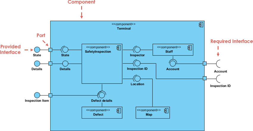
The example above shows the INTERNAL COMPONENTS of a LARGER COMPONENT:
-
The DATA (account and inspection ID) FLOWS into the component via the PORT on the right-hand side and is CONVERTED into a format the internal components can use. The interfaces on the right are known as REQUIRED INTERFACES, which represents the SERVICES the component needed in order to carry out its duty.
The data then passes to and through several other components via various connections before it is OUTPUT at the ports on the left. Those interfaces on the left are known as PROVIDED INTERFACE, which represents the SERVICES TO DELIVER by the exhibiting component.
雖然說是 required/provided interface,聽起來是 service,但這裡的說法 (data flows into ...) 及圖例,interface 可以是 data 或 service,也因此 component diagram 是可以表現 data flow 的。
從上面 need-to-known basis 的角度來看,是 required interface 的一方需要知道 (內部會用到) provided interface,但並不表示資料是 requried 往 provided 一方拉取,還是 provided 往 required 一方推送,這屬於實作細節了。
-
It is important to note that the internal components are surrounded by a large 'box' which can be the OVERALL SYSTEM itself (in which case there would not be a component symbol in the top right corner) or a SUBSYSTEM or component of the overall system (in this case the 'box' is a component itself).
Component 可大可小,端看位在哪個層次看這個 system being modeled。
-
Basic Concepts of Component Diagram
-
A component represents a MODULAR PART of a system that ENCAPSULATES its contents and whose manifestation is replaceable within its environment. ??
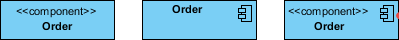
In UML 2, a component is drawn as a rectangle with optional compartments stacked vertically. A high-level, abstracted view of a component in UML 2 can be modeled as:
- A rectangle with the component's name
- A rectangle with the component icon
- A rectangle with the stereotype text and/or icon
Interface
-
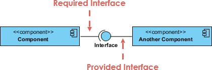
In the example below shows two type of component interfaces:
-
Provided interface symbols with a COMPLETE CIRCLE at their end represent an interface that the component provides - this "lollipop" symbol is shorthand for a REALIZATION RELATIONSHIP of an interface classifier.
"classifier" 指的好像是
<<interface>>的用法,但那不是 stereotype 嗎 ?? -
Required Interface symbols with only a HALF CIRCLE at their end (a.k.a. sockets) represent an interface that the component requires (in both cases, the interface's name is placed near the interface symbol itself).
習慣上 interface name 只會寫在 provided interface 這一方 ??
-
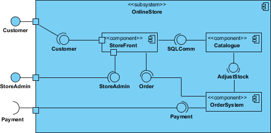
Component Diagram Example - Using Interface (Order System)
Subsystems
-
The subsystem classifier is a specialized version of a component classifier. Because of this, the subsystem notation element inherits all the same rules as the component notation element. The only difference is that a subsystem notation element has the keyword of subsystem instead of component.
Port
-
Ports are represented using a square along the edge of the system or a component. A port is often used to HELP EXPOSE required and provided interfaces of a component.
感覺有點多餘?
-


手冊: