Add FLY_SUPER8 and FLY_D8 board #27580
Conversation
|
@Fly3DTeam Why are you not adding the Fly D8 Pro? |
8d102d6 to
852e197
Compare
add FLY_D5, FLY_DP5, FLY_D7, FLY_D8_PRO, FLY_SUPER8_PRO, FLY_CDY_3 BOARD
Added |
|
D5/DP5/D7, Currently, the UART mode of TMC cannot be used. |
That's great, well done. It's probably best for most users to link to the English pages. The schematic given for the Fly D8 Pro (STM32H723) is wrong, it's the schematic of the D8 (STM32F407). |

|
I had a quick look at the D9 Pro pinout, it seems correct except for the temperature section: You could also add the FDCAN pins: You can define the driver UART and SPI pins like this: Is there a bootloader to flash the Marlin firmware via a USB stick in one of the USB ports? |
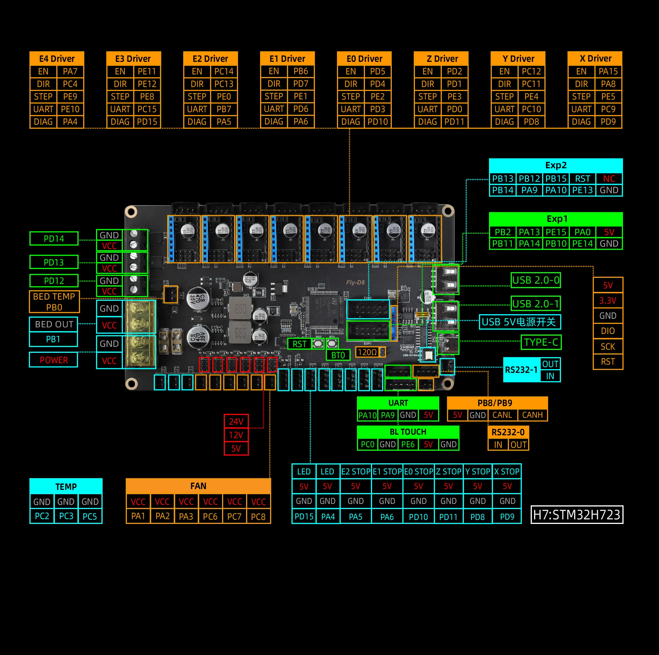
A schematic diagram shared by D8 and D8PRO. Because the 100-pin chip of F4 is slightly different from that of H7, please refer to the pin diagram in the documentation manual. |
Ok, thanks for the reply, DFU will always work, USB firmware flashing would be very appreciated by many users. I see a few issues in the variant board definition. and enable the FDCAN port (add to build_flags): |
|
The given pinout for D8 Pro EXT1 and EXT2 connectors seem to be wrong. How about this: So I guess the FLY D8 pinout is also wrong: |

|
I tried to compile Marlin based on the provided files for the Fly D8 Pro and Fly Super 8 Pro. Both configurations cannot compile. |
|

I set the serial ports correctly before compilation, that is not the cause of the compilation error. Thanks for correcting the EXP port pinouts. Unfortunately the D8 PRO EXP1 still has an obvious mistake, at least if I check it on a D8 Pro V1.1, perhaps it's correct for a V1.0 board. |

There was a problem hiding this comment.
The D8 Pro configuration does not work well. Lot's of issues, needs testing...
On the D8 pro, can you get all stepper drivers to work with your configuration? Serial and SPI on all 8 steppers? I cannot, which is a known issue for the STM32H7, and there are solutions/workarounds.
Have a look at the BTT SKR 3.0, I'm using something closer to that configuration with good results. 新年好!
Does the SPI mode for TMC work? What's the reason UART mode for TMC doesn't work? |
SPI is valid. We guess it may be due to a timer, which keeps getting stuck at the test drive. |
3ba4774 to
8771545
Compare
|
Are you sure about the PB2 pin on EXT1 of the D8 Pro? |
|
According to Images on https://www.aliexpress.com/item/1005007765975184.html
You can magnify it and barely make out that the H7 has PB2, while the F4 has PB1 So presuming the silkscreen is correct... I agree that EXP1_02_PIN on Marlin/src/pins/stm32h7/pins_FLY_D8_PRO.h seem to be wrong. Currently it has Looks like it should be |

|
I have 3x Fly D8 Pro V1.1 (H723), the board says "V1.1" which is NOT shown in the image provided in the link above (https://mellow.klipper.cn/en/assets/images/pin-1652261e2a5a0010adec2b02087c5fff.webp). So I think that the provided pinout picture, schematic and silkscreen are all wrong. Additionally, the provided board variant files cause lots of issue for me. Many devices are disabled, and some devices are added on GPIOF, which is not present on the 100 pin chip. This needs a good review. |
I checked and found that the pinout is wrong and a fix has been arranged. What do you mean by "some devices are added to GPIOF"? |
About the variant for Fly D8 Pro (H723): About PeripheralPins.c, there is still an issue. Below a sample. Most devices are commented out, which makes them inaccessible to Marlin. Like the UART TX pin, only LPUART1 is left which is not supported by SERIAL_DMA. The same pins can also be used as USART1, which supports SERIAL_DMA, but those lines are commented out. Question: Can all stepper drivers use serial and SPI stepper communication? I tried it previously, but could not get any of the E-stepper to work. Below some lines of PeripheralPins.c to illustrate the issues mentioned: |
2fedeaa to
ab24764
Compare
ab24764 to
036c390
Compare
|
@Fly3DTeam — Overall this is good! There are just two fixes that would make this better for users…
It will be great to have these boards included in the 2.1.3 release. Have a look at these final details, and let me know when it is ready! |
About the FLy D8 Pro, it comes with the Katapult bootloader, which will be overwritten by Marlin in the current configuration (both start from 0x08000000). Katapult will continue boot from 0x082000000, so Marlin could be stored there to preserve the bootloder. Unfortunately the board does not have a SD card slot, and the 3 USB ports cannot be used to flash a firmware from a USB stick because of the onboard hub which has the upstream port at the USB Type C port which means that the STM32H723 USB can only work in device mode. |
For motherboards without SD card slots, we usually use DFU+STM32CubeProgrammer to burn marlin firmware (the link to the method has been added to the pin file of the corresponding motherboard) |
|
It's not unusual for board contributions to be built on the output from |
|
I just gave the D8 Pro (STM32H723) another try. I encountered timer conflicts. After I solve those(-DTIMER_SERVO=TIM5 -DTIMER_TONE=TIM2) I found all 8 stepper drivers (3x SPI + 5x uart) communicating correctly. |
I've updated the timers on the D8 Pro build environment. Any others? We can add comments in pins files to correct bad documentation from the manufacturer.
For the rest everything seems to be working fine out of the box now. The Marlin pins file is correct, and that is what counts. |
Submitting a Pull Request
Added marlin support for FLY_D5,FLY_DP5 ,FLY_D7 ,FLY_D8 ,FLY_D8_PRO,FLY_SUPER8 ,FLY_SUPER8_PRO ,FLY_CDY3
Description
Below are links to motherboard information.
FLY_D5 :https://mellow.klipper.cn/docs/category/fly-d5
FLY_DP5 :https://mellow.klipper.cn/docs/ProductDoc/MainBoard/fly-d/fly-dp5/
FLY_D7 :https://mellow.klipper.cn/docs/ProductDoc/MainBoard/fly-d/fly-d7/
FLY_D8 :https://mellow.klipper.cn/docs/ProductDoc/MainBoard/fly-d/fly-d8-f407/
FLY_D8_PRO :https://mellow.klipper.cn/docs/ProductDoc/MainBoard/fly-d/fly-d8-h723/
FLY_SUPER8 :https://mellow.klipper.cn/docs/ProductDoc/MainBoard/fly-super/fly-super8/
FLY_SUPER8_PRO : https://mellow.klipper.cn/docs/ProductDoc/MainBoard/fly-super/fly-super8-pro/
FLY_CDY3:https://mellow.klipper.cn/docs/ProductDoc/MainBoard/fly-cdy/fly-cdy-v3/
Related Issues
D5/DP5/D7, Currently, the UART mode of TMC cannot be used.